• ⌛PRE-ORDER
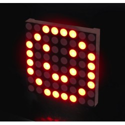
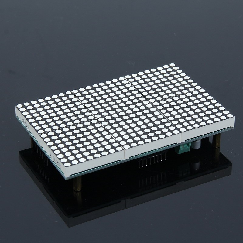
16x24 Red LED Matrix Panel - Chainable HT1632C Driver
search
  • 16x24 Red LED Matrix Panel - Chainable HT1632C Driver
  • 16x24 Red LED Matrix Panel - Chainable HT1632C Driver
  • 16x24 Red LED Matrix Panel - Chainable HT1632C Driver

16x24 Red LED Matrix Panel - Chainable HT1632C Driver

$24.49

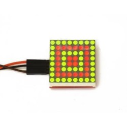
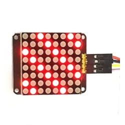
3.3V and 5V LED Matrix Module with 16x24 pixels and HT1632C driver measuring 75.6mmx113.5mm.

Quantity

  Security policy

(edit with the Customer Reassurance module)

  Delivery policy

(edit with the Customer Reassurance module)

  Return policy

(edit with the Customer Reassurance module)

Features:

  • 16x24 pixel LED Matrix
  • Color: Red
  • Operating Voltage: 2.4V - 5.5V DC
  • Number of Pixels: 384
  • Driver: HT1632C
  • 3-pin Serial protocol (similar to SPI)
  • Adjustable display brightness
  • Can be set to flash at 1Hz
  • Cascadable design
  • Fully assembled
  • Control via 3 digital output pins on your microcontroller
  • Arduino and Raspberry Pi compatible
  • Dimensions: 75.6mm x 113.5mm
  • Operating Temperature: 0 - 45C
  • Power Consumption: <1.8W
  • Static display which does not need real-time scanning
  • Supports both parallel and series cascading for seamless connections in any direction
  • Pixel Size: 3.75mm
  • Pinout:
    • VCC: Power Input (2.4V - 5.5V DC)
    • GND: Ground 0V
    • DAT: Serial Data Input
    • #WR: WR Write Clock Input (Data on the DATA lines are latched into the HT1632C on the rising edge of the WR signal)
    • #RD: RD Read Clock Input (The HT1632C RAM data is clocked out on the falling edge of the RD signal. The clocked out data will appear on the DATA line. The host controller can use the next rising edge to latch the clocked out data.)
    • #SC: SC Select Chip (When the SC line is high, the data and command read from or written to the HT1632C is disabled, and the serial interface circuit is also reset. If SC is low, the data and command transmission between the host controller and the HT1632C are all enabled.
    • OSC: If the RC Master Mode command is programmed, the system clock source is from on-chip RC oscillator and system clock is output to OSC pin. If the Slave Mode or EXT CLK Master Mode command is programmed, the system clock source is input from external clock via the OSC pin.
    • SYN: If the RC Master Mode or EXT CLK Master Mode command is programmed, the synchronous signal is output to SYN pin. If the Slave Mode command is programmed, the synchronous signal is input from SYN pin. 


Connection for Raspberry Pi:

RPI LabelPinSURE LabelPin
GND 6 GND 8
5V 4 5V 16
GPIO 10 (MOSI) 19 DAT 7
GPIO 11 (SCLK) 23 WR 5
GPIO 8 (CE0) 24 OSC 2
GPIO 7 (CE1) 26 SC 1


Connection to Arduino:

  • VCC to +5V
  • GROUND to Ground
  • DAT to D2
  • WR to D3
  • SC to D4
TS2197
Comments (0)
No customer reviews for the moment.