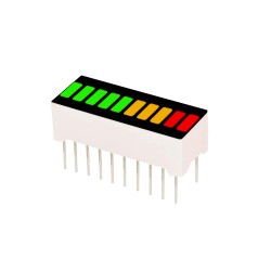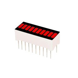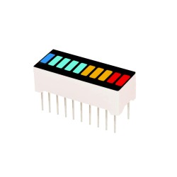
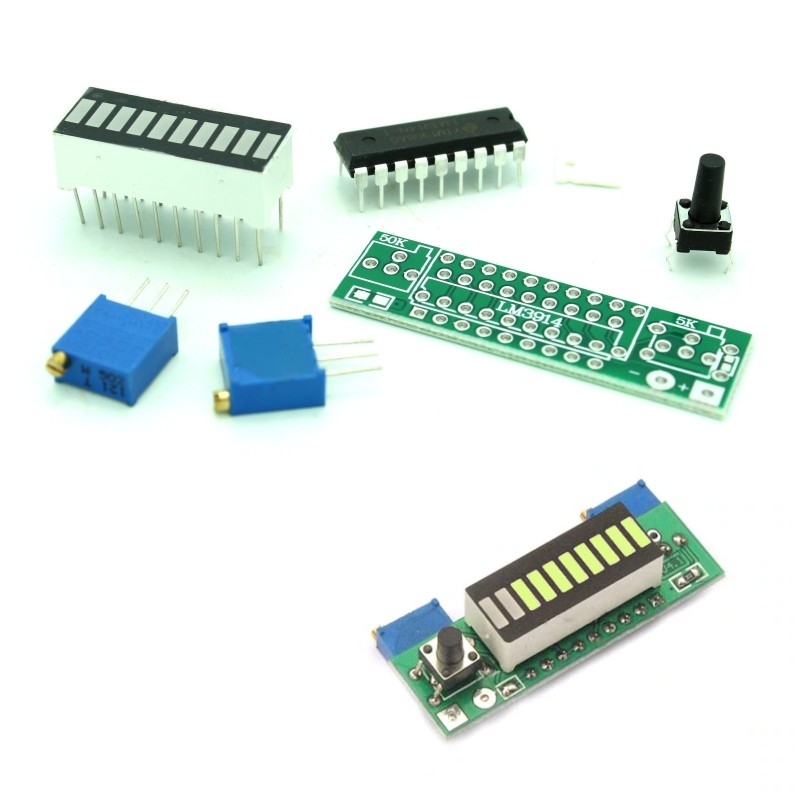


This LED bar graph module comes with the LM3914 controller chip and the LED Bar Graph on a single PCB! Useful for battery meters, sound bars and other projects where visual measurements are key. 2.4V to 20V adjustable range. Just turn the dials to set the range and as the voltage increases, the LED bar graph lights up.
 Security policy
(edit with the Customer Reassurance module)
 Delivery policy
(edit with the Customer Reassurance module)
 Return policy
(edit with the Customer Reassurance module)
Features:
High and low voltage battery display range references:
1. Lithium battery:
After the completion of a single lithium battery discharge voltage is 3V, when fully charged 4.2V;
1S correspond to 3V (first light) to 4.2V (tenth lights);
2S corresponds to 6V (first light) to 8.4V (tenth lights);
3S correspond to 9V (first light) to 12.6V (tenth lights);
4S correspond to 12V (first light) to 16.8V (tenth lights);
Other series voltage and so on.
2. Lead Acid Batteries
6V or 12V lead-acid battery is generally:
6V corresponds to 4.8V (first red light) to 6.75V (tenth lights);
12V corresponds to 9.6V (first red light) to 13.5V (tenth lights);
Set the dials for high and low thresholds according to the above standard battery discharge ranges to accurately display the battery level at all times
How to adjust the voltage range:
Equipment needed: an adjustable power supply and a small flathead screwdriver.
For example: For a single 3.7V lithium, 3V is empty, 4.2V is full.
1, Adjust the power supply voltage to the desired full voltage in this example, 4.2v.
2. Connect to the board. 3. If the LEDs are not on or partially on, slowly adjust 503 (50k) potentiometer counterclockwise until the LED strip just lights up completely. If the LEDs are all on, slowly adjust 503 (50k) clockwise until one led goes off and then turn back counterclockwise so it just lights up completely.
4, Adjust the power supply voltage to the desired low voltage, in this example 3V. Adjust 502 (5K) potentiometer to just light a single LED. If it does not light turn clockwise, several or all lit turn counterclockwise.
5, Repeat the first 4 steps. Usually 2 repetitions is sufficient to adjust to the desired display range.
Display Mode A / P: full brightness linear / single lamp lattice mode switch, the default is a linear model, the board set aside a switch pad, even with soldering pads can be turned into full light linear mode, no welding is the point like single light display
Note:
To adjust the voltage range, first set the high voltage, then adjust the low end. + is positive, - is negative. Max voltage: 20V DC
Specifications:

This LED bar graph module comes with the LM3914 controller chip and the LED Bar Graph on a single PCB! Useful for battery meters, sound bars and other projects where visual measurements are key. 2.4V to 20V adjustable range. Just turn the dials to set the range and as the voltage increases, the LED bar graph lights up.