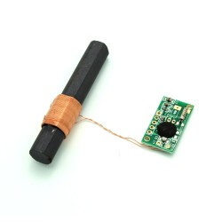
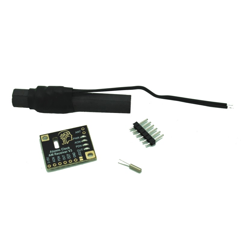


Always have accurate UTC time for your projects and Atomic Clocks. Use this receiver module to receive the 60kHz radio time in the United States. Ferrite antenna included. Comes soldered or as a kit. Works with 3.3V, 5V, 12V etc. 3V to 15V DC.
 Security policy
(edit with the Customer Reassurance module)
 Delivery policy
(edit with the Customer Reassurance module)
 Return policy
(edit with the Customer Reassurance module)
Features:
Pinout:
Reference: http://www.nist.gov/pml/div688/grp40/wwvb.cfm
Sample Arduino Code:
// WWVB coverage:
// http://tf.nist.gov/stations/wwvbcoverage.htm

/*
  Pinout

  Supply voltage range is 3V-15V
  Normal operation has PDN connected to ground.
  In standby mode, PDN is connected to Vdd
  OUT is the input to WWVB_PIN - no pullup required

VCC   - Supply voltage +5V
GND   - Ground
OUT - Time pulse to Arduino pin 2 (no pullup)
PDN  - HIGH: RCVR OFF, LOW: RCVR ON. If you leave this pin floating it is HIGH.
      Normally just connect this to ground so the receiver is always on.
      If this pin is switched from HIGH to LOW it resets the
      receiver.

  There are consecutive position markers at the 59th and 0th
  seconds which allow synchronisation.
  The change in the pulse starts exactly on the second
  (unlike WWV which also has a "tick" in all but two seconds).
  A position marker is 0.8s of low power
  A one is 0.5s of low power
  A zero is 0.2s of low power
*/


// OUT is connected to this pin. OUT is the inverted output signal.
#define WWVB_PIN 2

// Flashes in sync with receiver pin
#define LED_PIN LED_BUILTIN

void setup(void)
{
  Serial.begin(9600);
  while(!Serial);

  pinMode(LED_PIN, OUTPUT);

// Don't set the internal pullup
  pinMode(WWVB_PIN, INPUT);

  Serial.println("Start");
}

void loop(void)
{
  if(digitalRead(WWVB_PIN)) {
    digitalWrite(LED_PIN,HIGH);
  } else {
    digitalWrite(LED_PIN,LOW);
  }
}
Specific References
Always have accurate UTC time for your projects and Atomic Clocks. Use this receiver module to receive the 60kHz radio time in the United States. Ferrite antenna included. Comes soldered or as a kit. Works with 3.3V, 5V, 12V etc. 3V to 15V DC.