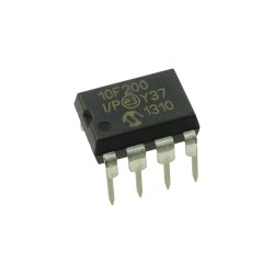
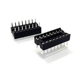
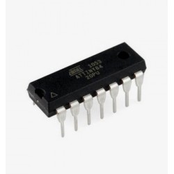
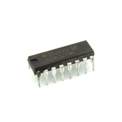
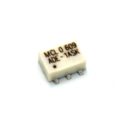
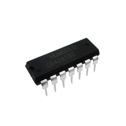
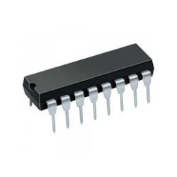
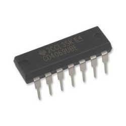
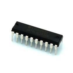
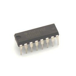
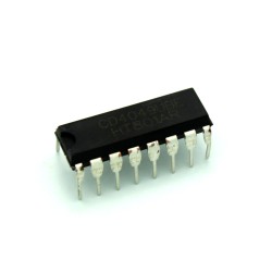
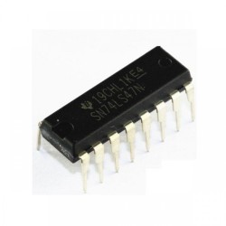
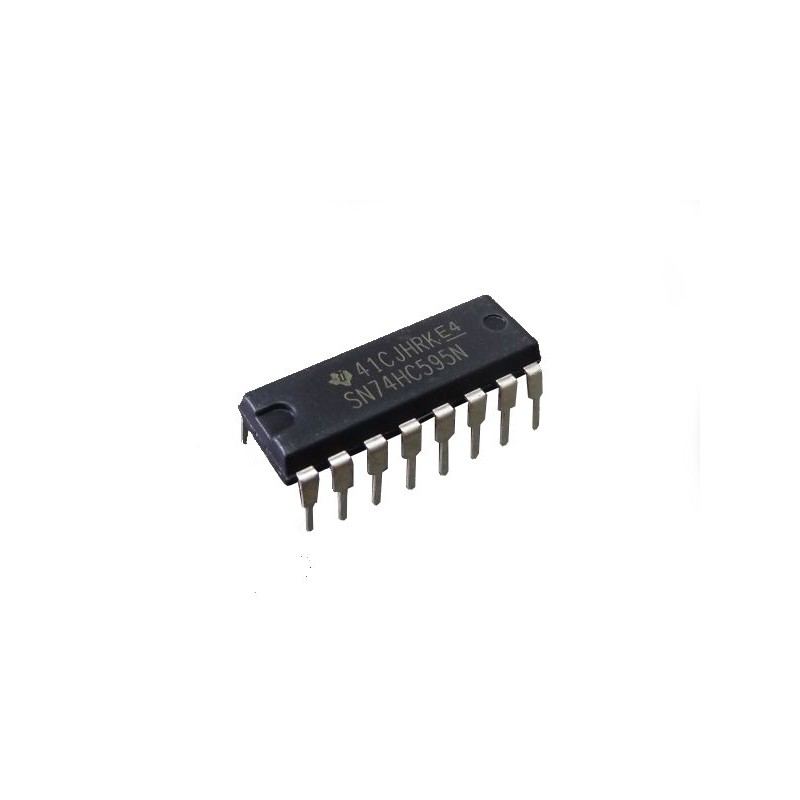
This 8 Bit Shift Register gives you the ability to store in 8 bits of data sent in one at a time and feed them out to 8 corresponding output pins. This is most useful for using 1 pin of a microcontroller to control 8 objects by sending the 8 signal values in serially and latching them to output the values in parallel.
Quick Getting Started Pin Hookup Explained:
- Pin 14: Data (SER)
- This is the pin you will send the 8 bits of data on serially.
- Pin 11: Clock (SRCLK)
- This is the pin you will turn on and off after each bit of data sent serially. It tells the IC when you have finished transmitting 1 bit of data and it should be stored into your 8 bit sized memory.
- Pin 12: Latch (RCLK)
- This is the pin you will set on when you have finished transmitting all 8 bits of data. It will transfer what you have in your 8 bit sized memory to the 8 output pins. More about the output pins below.
- Pin 15: Output Bit 1 (QA)
- This bit contains the last bit of data sent serially. This is the first one to get written and it's value gets shifted to Output Bits 2-8 respectively every time the Clock pin is triggered.
- Pin 1: Output Bit 2 (QB)
- Pin 2: Output Bit 3 (QC)
- Pin 3: Output Bit 4 (QD)
- Pin 4: Output Bit 5 (QE)
- Pin 5: Output Bit 6 (QF)
- Pin 6: Output Bit 7 (QG)
- Pin 7: Output Bit 8 (QH)
- This bit contains the first bit of data sent serially. For example, if you sent 8 bits one after the other, this will be the first one you sent over.
- Pin 16: Power (VCC)
- This pin provides power to the chip. Give it 2V - 6V
- Pin 8: Ground (GND)
- This pin is Ground for the chip. Give it 0V
- Pin 13: Output Disable (OE)
- When this pin is set to high, all outputs are disconnected.
- Pin 10: Clear Shift Register (SRCLR)
- When this pin is set to low, the values in the shift register (your 8 bit sized memory) are cleared.
- Pin 9: The next bit to be shifted out (QH')
- You will use this pin when daisy chaining Shift Registers to eachother (for example, to make a 16 bit shift register you'll daisy chain 2 of these chips). This pin will be the input to the next shift register.
Specifications:
- 8 Bit Serial In, Parallel Out Shift
- Operating Voltage: 2V - 6V
- High Current 3-State Outputs Can Drive up to 15 LSTTL Loads
- Low Power Consumption, 80uA Max
- Typical Tpd = 13 ns
- 6 mA Output Current at 5V
- Low Input Current: 1uA Max
- Number of Pins: 16
- Operating Temperature Range: -40 to 85 C
- Manufacturer Part Number: SN74HC595N
Click here to download the Datasheet.



 Security policy
 Delivery policy
 Return policy