Christmas Ornament DIY Soldering Kit Decoration Electronic LED Red Learn to Solder
search
  • Christmas Ornament DIY Soldering Kit Decoration Electronic LED Red Learn to Solder
  • Christmas Ornament DIY Soldering Kit Decoration Electronic LED Red Learn to Solder
  • Christmas Ornament DIY Soldering Kit Decoration Electronic LED Red Learn to Solder
  • Christmas Ornament DIY Soldering Kit Decoration Electronic LED Red Learn to Solder
  • Christmas Ornament DIY Soldering Kit Decoration Electronic LED Red Learn to Solder
  • Christmas Ornament DIY Soldering Kit Decoration Electronic LED Red Learn to Solder
  • Christmas Ornament DIY Soldering Kit Decoration Electronic LED Red Learn to Solder
  • Christmas Ornament DIY Soldering Kit Decoration Electronic LED Red Learn to Solder
  • Christmas Ornament DIY Soldering Kit Decoration Electronic LED Red Learn to Solder

Christmas Ornament DIY Soldering Kit Decoration Electronic LED Red Learn to Solder

$7.99
✅SHIPS TODAY

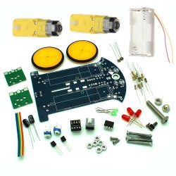
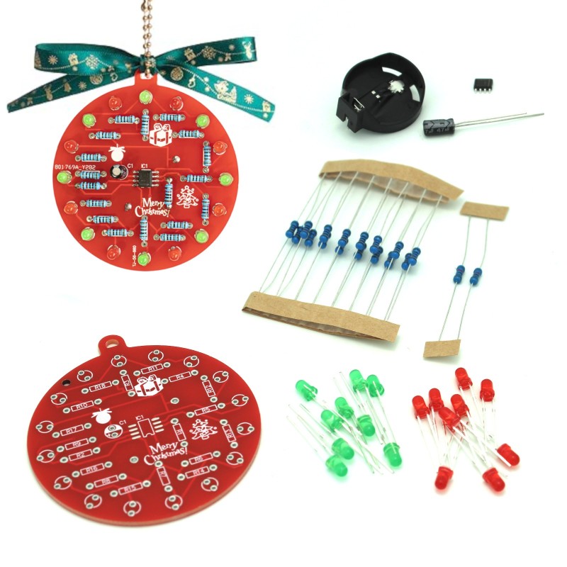
Solder together your very own light up Christmas Ornament! Add some electronic sophistication to your tree or give as a gift for the tinkerers in your life! Makes a great ornament for electronics professionals that has red and green blinking lights to add a twinkle to your tree.

Quantity

  Security policy

(edit with the Customer Reassurance module)

  Delivery policy

(edit with the Customer Reassurance module)

  Return policy

(edit with the Customer Reassurance module)

Features:

  • Miniature Xmas gadget
  • Light up LED ornament kit
  • Requires soldering to put it together
  • Show off your electronic soldering skills with this neat little project
  • Great for techies, engineers, designers, programmers, electronic artists, etc.
  • 16 LEDs to solder on for practice!
  • Ornament can be hung (e.g. in the window or Xmas tree) or can be worn as a badge
  • Great attention grabber
  • LED Christmas Tree Decoration Soldering Kit
  • Educational: designed to teach the basics of through-hole soldering and circuit design
  • Attractive Design: Features blinking red and green lights, perfect for hanging on Christmas trees, backpacks, or windowsills. Makes a wonderful gift.
  • Ideal for Various Users: Suitable for beginners, school experiments, parent-child teaching, and friends interested in crafts or science.

Specifications

  • power supply: 3V (battery sold separately: Coin Cell Battery)
  • operating temperature: -40C to 85C (−40F to 185F)
  • dimensions: 2.40 x 2.16 inches

How it works:

  • R1, R2, and C1 are connected to the NE555 integrated circuit, forming a multi harmonic oscillator circuit.
  • The circuit outputs high and low signals at approximately 1 Hz through pin 3.
  • When pin 3 outputs a low level, LED1-8 light up; when it outputs a high level, LED11-18 light up.
  • LEDs 1-16 are arranged in a cross row, using red and green colors alternately.
  • Once powered on, the circuit creates a flowing, flashing light effect.

Assembly Instructions:

  1. Organize Components: Arrange all parts (LEDs, resistors, capacitor, NE555 IC, Battery Holder) so you can see everything
  2. Install 10K Resistors: Solder the two 10K resistors (brown, black, black, red, brown) onto the PCB in slots R1 and R2.
  3. Install 1K Resistors: Solder the sixteen 1K resistors (brown, black, black, brown, brown) onto the PCB in slots R3 and R18.
  4. Place Red and Green LEDs: Insert the LEDs into the board in alternating color starting with red at the top of the board. Place them all around the edges aligning their polarities (longer leg = positive) so the positive legs are closest to the outer edge of the board. Solder each in its position.
  5. Install 555 Timer IC: Place the NE555 IC on the PCB and solder it securely. Make sure the notch on the circuit board matches the notch on the chip.
  6. Attach Capacitor: Solder the capacitor C1 as indicated. Ensure proper orientation for polarized capacitors where the longer leg is + and - is labeled on the capacitor.
  7. Install Battery Holder: Attach and solder the battery holder on the back of the board. Make sure the notch is in the marked position as printed on the circuit board.
  8. Inspect Connections: Double-check all solder joints for completeness and potential short circuits.
  9. Test the Circuit: Plug the battery into the battery socket on the back and enjoy the LED light show! Congrats!

Additional Resources: Helpful Assembly Instruction Video: https://www.youtube.com/watch?v=aWcp5OjzusI&t=14s

TS4296
35 Items
Comments (0)
No customer reviews for the moment.