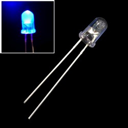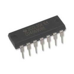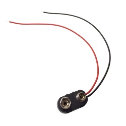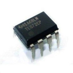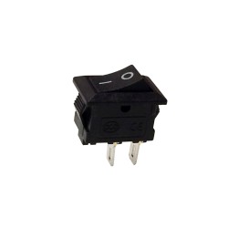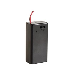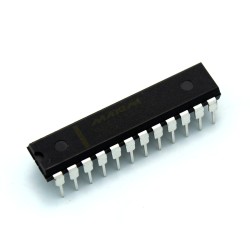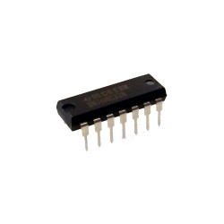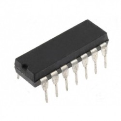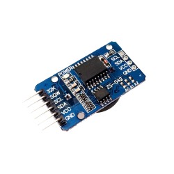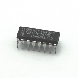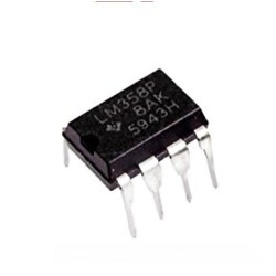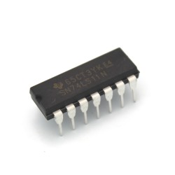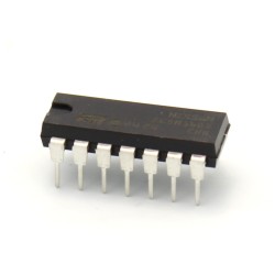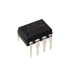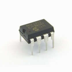
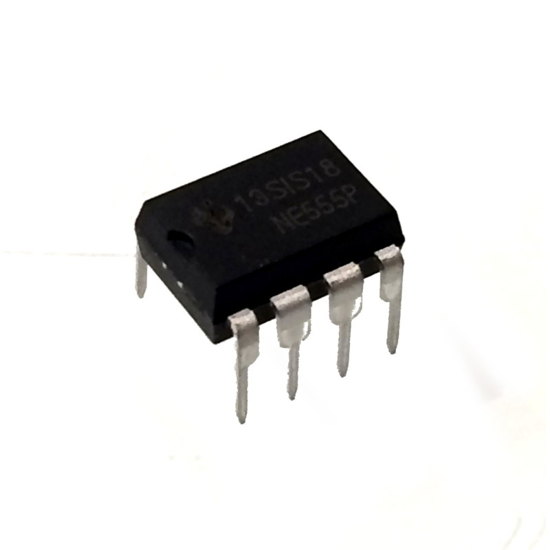


Want to make your LED blink for a set time, use this nifty little timer. This is one of the most versatile chips in terms of hobbyist project uses. If you want to have something triggered at a set time or just want to get your feet wet using ICs, use this little timer.
 Security policy
(edit with the Customer Reassurance module)
 Delivery policy
(edit with the Customer Reassurance module)
 Return policy
(edit with the Customer Reassurance module)
555 timers have so many uses in hobbyist projects, they just count time pass to give you very accurate time delays. The output oscillates from LOW to HIGH with variable speed depending on the inputs you feed it.
| Pin | Name | Purpose |
|---|---|---|
| 1 | GND | Ground reference voltage, low level (0 V) |
| 2 | TRIG | The OUT pin goes high and a timing interval starts when this input falls below 1/2 of CTRL voltage (which is typically 1/3 of VCC, when CTRL is open). |
| 3 | OUT | This output is driven to approximately 1.7 V below +VCC or GND. |
| 4 | RESET | A timing interval may be reset by driving this input to GND, but the timing does not begin again until RESET rises above approximately 0.7 volts. Overrides TRIG which overrides THR. |
| 5 | CONT | Provides "control" access to the internal voltage divider (by default, 2/3 VCC). |
| 6 | THRES | The timing (OUT high) interval ends when the voltage at THR is greater than that at CTRL (2/3 VCC if CTRL is open). |
| 7 | DISCH | Open collector output which may discharge a capacitor between intervals. In phase with output. |
| 8 | VCC | Positive supply voltage, which is usually between 3 and 15 V depending on the variation. |
Specifications:
Want to make your LED blink for a set time, use this nifty little timer. This is one of the most versatile chips in terms of hobbyist project uses. If you want to have something triggered at a set time or just want to get your feet wet using ICs, use this little timer.